Low-Cost Design Techniques for CNC Machining
CNC machining involves removing materials from a solid block using a high-speed rotating cutting tool to produce the required parts according to the drawings. The cutting tool plays a crucial role in CNC machining as it directly contacts the part and removes the excess material to obtain the desired component.
The most common CNC cutting tools, such as end mills and drill bits, have cylindrical shanks, a certain tip shape, and a limited cutting length. These two characteristics of the cutting tool limit its cutting ability, making it unable to machine deep small holes and undercuts. The following are some commonly used cost-saving design techniques:
I. Precautions for the Minimum Radius (R Angle)
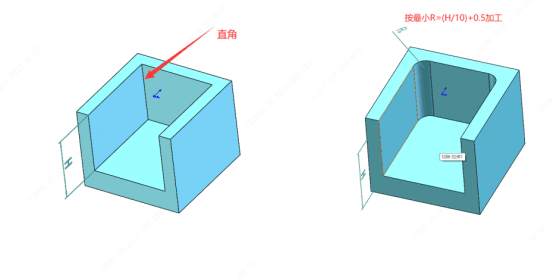
CNC milling cutters have a cylindrical shape. When cutting an inner wall, a radius will appear at the vertical corner. Smaller tools need to perform multiple cuts at a lower speed to achieve a small radius, which will result in more machining time and higher costs.
Therefore, when designing parts to be manufactured by CNC machining, it is advisable to increase the radius of the cavity depth and use a similar radius for the inner edges. If you do not provide a 2D drawing with specific instructions for corner cleaning at the right angle, our company will process the minimum R angle for all the right angles of the inner cavities of the workpiece according to the following rules:
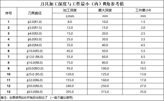
Suppose the diameter of the cutting tool is ∮D mm, the maximum depth of the inner cavity is H mm, and the minimum inner R mm is R. The formula is R = (H/10) + 0.5, and ∮D = H/5. For example, if the depth of the inner cavity is 30 mm, the minimum inner R that can be processed is R3.5 mm = (30/10) + 0.5, and the corresponding cutting tool diameter is ∮6 = 30/5. Currently, the smallest inner R we can achieve is R0.5 with a depth ≤ 3 mm. The smaller the inner R, the smaller the required cutting tool, and the higher the machining cost.
Our platform recommends making the R angle as large as possible when allowed!
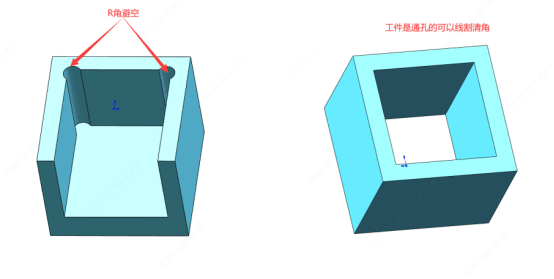
If you need the workpiece to retain a right angle, please provide a 2D drawing with clear markings. In this case, it requires EDM (Electrical Discharge Machining) for corner cleaning (corner cleaning requires CNC machining of a copper electrode first and then EDM processing on the EDM machine, which is costly). Alternatively, you can change the structure of the workpiece to create an R angle clearance space, which can be directly processed by CNC machining at a lower cost. If the workpiece has through holes on both sides, it can be processed for corner cleaning on a wire electrical discharge machine, but the cost is also high.
II. Precautions for Threads
- To reduce communication costs and avoid machining errors, it is recommended that when designing, the threads should be designed according to the standard drilling inner diameter and rolling outer diameter, and the thread parameters should be completely described. When placing an order, try to include the inner and outer threaded workpieces in the same order for machining.
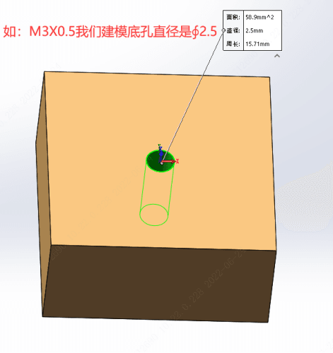
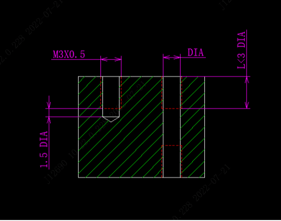
- Each engineer may draw the diameter of the thread bottom hole in the 3D drawing differently. For example, the standard diameter of the bottom hole for M3x0.5 is ∮2.5 (see the figure below). During programming, the bottom hole will be directly drilled according to ∮2.5, and then the automatic tapping machine will be used for tapping. If the bottom hole is drawn as ∮3, and the bottom hole is machined too large, it will be impossible to tap (in some cases, a threaded insert can be used for repair).
- For special threads, it is necessary to provide a physical sample for fitting.
- The strong thread connection occurs in the first few threads. Sometimes, a very long thread length is not necessary at all. A long threaded hole may require special tools and will take more machining time and cost. It is recommended that the thread length should not exceed 3 times the hole diameter. When the threaded hole is a blind hole, it is recommended to leave at least half of the hole diameter as the unthreaded length at the bottom of the hole.
III. Precautions for the Cavity Depth
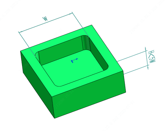
Machining deep cavities will greatly affect the cost of CNC parts because a large amount of material needs to be removed, which takes a very long time. The cutting length of CNC cutting tools is limited, and the best machining effect is achieved when the cutting depth reaches 2-3 times its diameter. For example, a ø12 milling cutter can safely cut a cavity up to 25 mm deep.
Cutting deeper cavities (5 times or more the diameter of the cutting tool) will lead to problems such as tool overhang, tool deflection, difficult chip removal, and tool breakage. Therefore, special tools or multi-axis CNC systems are required. In addition, when cutting a cavity, the tool must be tilted to the correct cutting depth, and enough space is needed for a smooth entry.
Limiting the depth of all cavities to 5 times their length (i.e., the maximum dimension in the XY plane) can achieve the minimum machining cost.
IV. Precautions for the Wall Thickness of Thin-Walled Parts
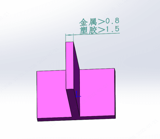
Thin-walled machining requires multiple passes at a low cutting depth, and it is prone to vibration, resulting in deformation or breakage. Therefore, it is difficult to accurately machine thin-walled parts, and the machining time will increase.
The wall thickness of metal parts is preferably designed to be above 0.8 mm (the minimum can be 0.5 mm), and the minimum wall thickness of plastic parts should be above 1.5 mm (the minimum can be 1 mm).
V. Precautions for Tolerances
The tighter the tolerance, the higher the machining cost because it increases the machining and quality inspection time.
If no specific tolerance is marked on the part drawing, the machining will be carried out according to the standard tolerance (±0.1 mm or higher). If there are special tolerance machining requirements, be sure to provide a 2D drawing and mark the corresponding tolerances.
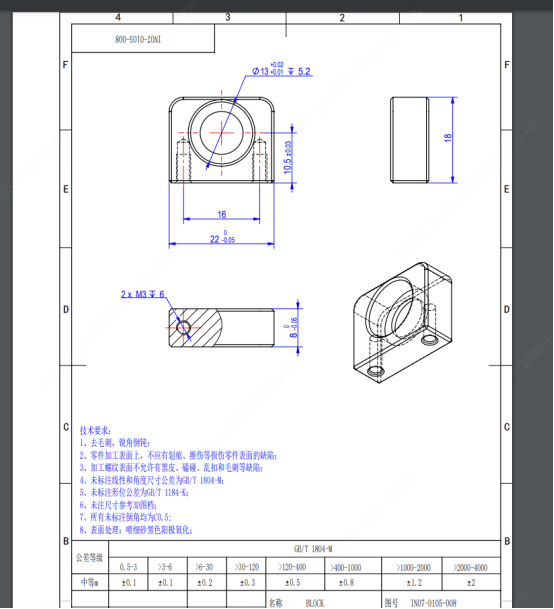
VI. Precautions for 2D Drawings
The 2D drawing is the best way to convey certain aspects of the design. Clearly marking the tolerances, surface roughness, assembly method, key inspection points, and quality control for the key features provides a reference for selecting the best machining method and process route, and the cost will also be lower.
For threaded holes and dimension depths, they also need to be marked simultaneously.
The engineering staff will also compare the 3D and 2D drawings during the drawing review. If there is any conflict, they can communicate and provide feedback in a timely manner.
CNC加工,一件起订,